
Scope
The purpose of the AFIPS Model is to provide a clear and repeatable structure for mapping Federal Information Processing Standards (FIPS) 140 validated cryptography to real systems. AFIPS focuses on how cryptography is selected, enforced, and evidenced across operating systems, validated modules, runtimes, applications, data services, networks, and key management. It is meant for architects, practitioners, and assessors who must align modern delivery practices with FIPS 140 requirements.
This document builds on the context established in the previous Automata publication on The CMVP and FIPS 140 2/3 which orients readers to the CMVP, Security Policies, and the role of FIPS 140 in federal assessments.
AFIPS organizes the layers of cryptography into eight layers:
- Layer 0 - Hardware Crypto Boundary
- Layer 1 - Platform OS and Policy
- Layer 2 - Validated Crypto Providers
- Layer 3 - Execution Environment
- Layer 4 - Applications and Middleware
- Layer 5 - Data Protection Services
- Layer 6 - Network and API Security
- Layer 7 - Key and Trust Management
The layers in this whitepaper are referred to as Layer (N) or L(N) with (N) representing any value from 0 through 7.
Definitions
FIPS - Federal Information Processing Standards.
Cryptographic Module - The set of hardware, software, and or firmware that implements approved cryptographic algorithms and key generation. It is contained within a defined cryptographic boundary and provides roles, services, self tests, and error handling consistent with FIPS 140.
Cryptographic Algorithm - A well defined procedure used to protect data or establish keys. In this paper the term covers approved algorithms for encryption, hashing, signatures, key agreement, and deterministic random bit generation, and any non approved but allowed algorithms used in approved key establishment modes.
Introduction to the Automata FIPS (AFIPS) Model
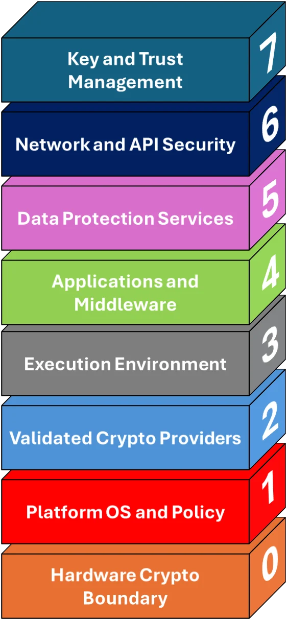
FIPS layers at a glance
AFIPS explains how cryptography is realized in practice. L2 provides the validated cryptographic module. L1 configures a platform policy that constrains algorithms and module selection. L3 hosts workloads that must resolve to the validated provider. L4 through L6 are where most cryptographic operations occur. L7 governs keys, trust anchors, and lifecycle.
Who uses this model
- Product and platform engineers
- Security architects and crypto SMEs
- SRE and platform teams operating federal workloads
- Assessors and authorizing officials
What this page covers
- Where crypto operations live: L4 through L6 call validated providers from L2. L2 uses L0 when hardware backed operations are required.
- Who enforces policy: L1 sets FIPS mode and system crypto policy. L3 controls admission and image integrity so workloads inherit the policy.
- Trust and lifecycle: L7 manages keys, attestation, rotation, separation of duties, archival, and destruction across the stack.
Why the AFIPS Model
Teams need a precise way to connect CMVP artifacts to design and control points. AFIPS standardizes that language so engineers and assessors reason about boundaries, approved algorithms, module selection, and evidence without guesswork.
The AFIPS Layer and Cryptographic Algorithms
By design, only L2 (crypto provider) and L0 (hardware) should execute cryptographic primitives. All other layers call into L2 or L0 through defined interfaces. As such, L2 and L0 are the only direct users of algorithms. Other layers are indirect users that consume those algorithms by invoking L2 or orchestrating L0 through handles.
Cryptographic algorithms such as AES or RSA can be mathematically strong, but the security you achieve in practice is determined by the cryptographic module that implements and exposes them. Vulnerabilities in the module, for example weak randomness, timing or cache side channels, and other known vulnerabilities can compromise the guarantees of even the strongest algorithms. Effective protection requires modules that enforce:
- Approved modes and suites.
- Run constant-time code where required.
- Protect keys with hardware.
- Manage key lifecycles and rotation correctly.
- Emit auditable evidence.
Within the AFIPS model, primitives execute only in L0 hardware and L2 providers, while higher layers invoke those services rather than reimplementing them. This separation lets L1 set policy, L3 enforce provider and suite selection, and L4 to L6 consume cryptography without handling raw secrets. Assurance improves when validated modules are bound to hardware roots of trust and continuously attested for configuration and version, for example through FIPS 140-3 validations, measured boot, SBOM pinning, and runtime attestation. Treat the algorithm as a specification and the module as the trust boundary, and design systems so that correct use is enforced by architecture, not by developer discipline.
Automata developed the AFIPS Core Rings to help contextualize the relationship between the underlying cryptographic algorithms and the modules which implement those algorithms.
AFIPS Core Rings
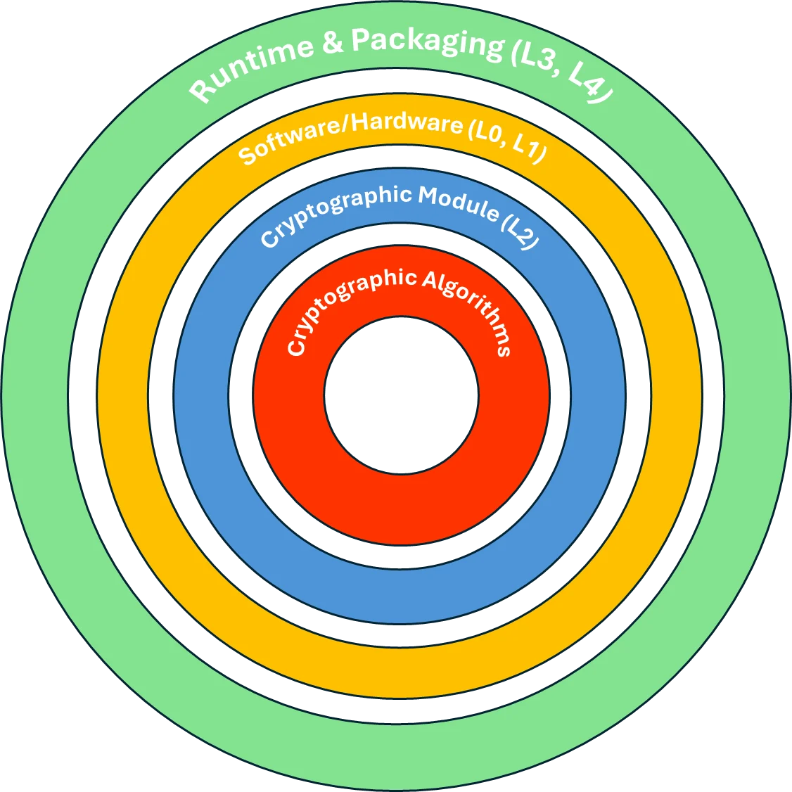
Think of cryptography as nested responsibility zones. Algorithms are at the core, implemented and enforced by a validated module. That module is selected and constrained by platform policy and is consumed by runtimes and applications. In practice, L4 through L6 call into L2 for AEAD, signatures, KDFs and hashing. L1 keeps the system in FIPS mode and restricts algorithms. L7 governs keys, rotation, audit, and attestation.
Algorithms: AES GCM or CCM, SHA 2 or 3, HMAC, HKDF, ECDSA or ECDH, RSA PSS, DRBG
Module: CMVP validated provider in approved mode with self tests
Platform: HSM or TPM, hardware RNG, and CPU instructions under OS policy
Runtime: Containers, VMs, serverless with SBOM pins and admission gates
Automata FIPS (AFIPS) Layers
| AFIPS Layer | Layer name | Purpose | FIPS focus |
|---|---|---|---|
| 7 | Key and Trust Management | Key lifecycle, trust anchors, attestation, certificates | Approved key establishment and wrapping, separation of duties, attestation of module state |
| 6 | Network and API Security | TLS, mTLS, IPsec, SSH, API gateways | Enforce approved cipher suites and certificate validation using a validated provider |
| 5 | Data Protection Services | Encryption at rest, tokenization, hashing, anonymization | Envelope encryption patterns using approved algorithms with keys from L7 |
| 4 | Applications and Middleware | Business logic, frameworks, service meshes, brokers | Use system or bundled validated providers. Avoid non approved algorithms and modes |
| 3 | Execution Environment | Containers, VMs, serverless runtimes | Images and runtimes resolve to validated providers and inherit OS FIPS policy |
| 2 | Validated Crypto Providers | Software or hardware modules that implement algorithms | Only CMVP validated modules in approved mode are present and selected at load time |
| 1 | Platform OS and Policy | Operating system and baseline crypto policy | OS is configured for FIPS mode and system crypto APIs use validated modules |
| 0 | Hardware Crypto Boundary | Physical roots such as HSMs, TPMs, true RNGs | Device is in scope and validated. Tamper resistance and self tests operate inside the boundary |
Layer 0 (L0): Hardware Crypto Boundary
Objective
Provide a physically and logically protected boundary for key storage and sensitive operations that must occur in hardware. Typical devices include HSMs, TPMs, smart cards, and other validated hardware modules.
Responsibilities
- Protect keys at rest inside the module boundary
- Provide true random number generation and approved DRBGs
- Perform sensitive operations such as unwrap, sign, and key derivation when required by policy
- Execute power up and conditional self tests and enforce error states
Common components
- Network HSMs, PCIe HSMs, embedded TPMs
- Hardware backed key stores in cloud or on premises
- Hardware entropy sources, sensors and tamper evidence
Implementation guidance
- Define and document the hardware boundary. Reference the module certificate and Security Policy
- Use approved mechanisms for key entry and output. Enforce separation of roles
- Bind hardware identities to platform attestation used by L7
Validation and evidence
- Reference CMVP certificate number and Security Policy
- Capture initialization procedures, self test logs, error handling, and tamper response
- Record inventory and serials for devices in scope
Common pitfalls
- Assuming a device is validated without checking the exact model, firmware, and certificate
- Operating in a configuration that is outside the Security Policy
- Mixing hardware and software keys without documented controls
Relationship to other AFIPS Layers
| From | To | Why this edge exists | Typical operations | Evidence |
|---|---|---|---|---|
| L2 | L0 | Hardware backed keys or RNG are mandated | Keygen, unwrap, sign in HSM or TPM. | HSM audit logs, module SP references, serials |
| L7 | L0 | Generate and hold sensitive roots in hardware | Root CA keys, KEKs. | Dual control procedures, device inventory |
Layer 1 (L1): Platform OS and Policy
Objective
Establish platform wide cryptographic policy that constrains algorithms and determines which modules are available to applications and runtimes.
Responsibilities
- Enable FIPS mode and restrict algorithms to approved and allowed sets
- Ensure system libraries and crypto APIs select validated modules
- Configure kernel and user space consumers such as TLS, IPsec, and SSH to enforce policy
Common components
- FIPS mode switches and crypto policy packages
- System crypto libraries and providers resolved by the OS
- Certificate stores, trust anchor packages, system wide TLS policy
Implementation guidance
- Document the OS version, crypto policy level, and the validated providers it resolves
- Disable non approved algorithms and curves. Remove or block unvalidated modules
- Ensure system services such as SSH and IPsec inherit the policy by default
Validation and evidence
- Configuration management showing FIPS mode and policy settings
- SBOMs and package manifests that identify the validated modules present
- Baseline hardening guides and automated policy checks
Common pitfalls
- Enabling FIPS mode but leaving non approved plugins available to workloads
- Building applications that statically link an unvalidated provider
- Allowing runtime flags to re enable non approved algorithms
Relationship to other AFIPS Layers
| From | To | Why this edge exists | Typical operations | Evidence |
|---|---|---|---|---|
| L1 | L2 | System selects only validated modules | FIPS mode, crypto policy packages. | OS settings, SBOM for provider packages |
| L1 | L3 | Runtimes inherit platform policy | Admission rules, image signing and verification. | Admission controller logs |
Layer 2 (L2): Validated Crypto Providers
Objective
Supply the approved cryptographic algorithms and key services through a CMVP validated module operating in approved mode.
Responsibilities
- Implement approved algorithms for encryption, hashing, signatures, key agreement, and DRBG
- Enforce self tests at power up and on demand. Enter and signal error states as required
- Provide clear versioning and configuration so the right module instance is selected at runtime
Common components
- Software providers validated under CMVP
- Hardware providers in HSMs and TPMs
- Language bindings and system wrappers that expose the provider to applications
Implementation guidance
- Pin to specific module versions listed in the certificate
- Configure the provider in approved mode only
- Map provider capabilities to application needs and remove any non required algorithms
Validation and evidence
- CMVP certificate and Security Policy references
- Configuration snippets that enable approved mode and disable non approved algorithms
- Self test logs and module selection logs at startup
Common pitfalls
- Assuming any build of a library is validated
- Using algorithms that are not approved in a particular mode
- Failing to prove the validated provider was actually selected at runtime
Relationship to other AFIPS Layers
| From | To | Why this edge exists | Typical operations | Evidence |
|---|---|---|---|---|
| L4 | L2 | Apps must not embed their own crypto | AEAD, HMAC, ECDSA verify, HKDF. | Provider load logs and approved mode flag |
| L5 | L2 | Data services centralize crypto choices | Envelope encryption, HMAC, SHA 2 or SHA 3. | Config pins to provider, algorithm allow list |
| L6 | L2 | Handshakes and channel protection | TLS 1.2 or 1.3 suites, ECDHE, RSA PSS, certificate path validation. | Gateway or mesh policy with suite list |
| L1 | L2 | System selects only validated modules | FIPS mode, crypto policy packages. | OS settings, SBOM for provider packages |
| L3 | L2 | Prove the right provider is active | Startup self test pass, provider version. | Runtime logs, env pins |
| L7 | L2 | Use approved wrapping and KDFs | RSA KTS, RSA OAEP, HKDF, PBKDF where approved. | Key wrap config and logs |
| L2 | L0 | Hardware backed keys or RNG are mandated | Keygen, unwrap, sign in HSM or TPM. | HSM audit logs, module SP references, serials |
Layer 3 (L3): Execution Environment
Objective
Ensure workloads inherit platform policy and actually use the validated provider at runtime.
Responsibilities
- Admit only signed and attested images, VMs, and functions
- Resolve crypto calls to the validated provider present on the host or in the image
- Prevent non approved providers from being loaded
Common components
- Container runtimes and image registries
- Virtual machines and hypervisors
- Serverless platforms and admission controllers
Implementation guidance
- Use image signing and verification. Fail closed when the required provider is missing
- Scan SBOMs for unvalidated crypto libraries and block on admission
- Provide runtime checks that demonstrate the provider loaded and approved mode is set
Validation and evidence
- Admission controller policies and logs
- Runtime logs showing provider selection and self tests
- SBOMs for images and golden VM templates
Common pitfalls
- Including an unvalidated crypto library in a base image
- Allowing dynamic plugin resolution that bypasses the validated provider
- Not capturing runtime evidence that proves approved mode
Relationship to other AFIPS Layers
| From | To | Why this edge exists | Typical operations | Evidence |
|---|---|---|---|---|
| L1 | L3 | Runtimes inherit platform policy | Admission rules, image signing and verification. | Admission controller logs |
| L3 | L2 | Prove the right provider is active | Startup self test pass, provider version. | Runtime logs, env pins |
Layer 4 (L4): Applications and Middleware
Objective
Use validated cryptography correctly in business logic and middleware while keeping cryptographic decisions centralized and auditable.
Responsibilities
- Call the platform provider through stable interfaces
- Enforce mTLS, certificate validation, and token verification using approved algorithms
- Avoid non approved algorithms and insecure modes
Common components
- Frameworks, service meshes, message brokers, caches
- Identity and access middleware that verifies tokens or assertions
- Application code that encrypts, signs, hashes, and derives keys
Implementation guidance
- Centralize crypto access through a thin wrapper that binds to the validated provider
- Use secure defaults from the Security Policy. Disable insecure cipher suites and curves
- Log cryptographic operations at a summary level for evidence without leaking sensitive data
Validation and evidence
- Code references that show provider bindings and approved algorithms
- Configuration for TLS, token validation, and message integrity
- Unit and integration tests that verify algorithm choices and error handling
Common pitfalls
- Pulling in a convenience library that bundles an unvalidated crypto implementation
- Accepting any certificate chain without policy checks
- Re enabling deprecated cipher suites for compatibility
Relationship to other AFIPS Layers
| From | To | Why this edge exists | Typical operations | Evidence |
|---|---|---|---|---|
| L4 | L2 | Apps must not embed their own crypto | AEAD, HMAC, ECDSA verify, HKDF. | Provider load logs and approved mode flag |
| L4 | L7 | Fetch verification keys or service certs | JWT or token verification, mTLS client certs. | Key ID match in logs |
Layer 5 (L5): Data Protection Services
Objective
Protect data at rest and in use with services that implement envelope encryption and related patterns using approved algorithms and keys from L7.
Responsibilities
- Provide encryption, decryption, and integrity services for data stores and filesystems
- Offer tokenization, hashing, and anonymization where required by policy
- Integrate with L7 for key generation, rotation, and access control
Common components
- Database or volume encryption features
- Object storage side encryption and client side encryption toolchains
- File level and application level encryption libraries
Implementation guidance
- Use envelope encryption with data encryption keys wrapped by key encryption keys from L7
- Select AEAD modes for confidentiality and integrity where supported
- Design for automated rekey and data rewrite for rotation events
Validation and evidence
- Configurations that show algorithm selection and key sources
- Rotation playbooks and audit logs for key use
- Demonstrations that non approved algorithms are not available
Common pitfalls
- Relying on default encryption that uses unapproved algorithms
- Mixing application keys and platform keys without a lifecycle plan
- Incomplete rotation and rewrap procedures
Relationship to other AFIPS Layers
| From | To | Why this edge exists | Typical operations | Evidence |
|---|---|---|---|---|
| L7 | L5 | Supply KEKs and rotation signals | DEK wrap or rewrap. | Rotation playbooks, wrap counts |
| L5 | L2 | Data services centralize crypto choices | Envelope encryption, HMAC, SHA 2 or SHA 3. | Config pins to provider, algorithm allow list |
Layer 6 (L6): Network and API Security
Objective
Protect data in transit and authenticate endpoints using approved cipher suites and validated certificate paths.
Responsibilities
- Enforce TLS and optional mTLS at service and edge layers
- Control cipher suites and protocol versions
- Validate certificate chains to trusted anchors from L7
Common components
- Load balancers, API gateways, and service meshes
- SSH and IPsec for administrative and network protection
- Reverse proxies and ingress or egress controllers
Implementation guidance
- Disable insecure protocol versions and suites. Prefer AEAD with forward secrecy
- Standardize certificate validation rules. Fail closed on policy violations
- Use hardware backed keys where required and record SNI and policy decisions for evidence
Validation and evidence
- Gateway and mesh configurations with explicit suites and protocols
- Certificate inventories and trust store baselines
- Logs that show handshake policy decisions
Common pitfalls
- Allowing legacy suites for compatibility without compensating controls
- Accepting wildcard or self signed certificates outside policy
- Not enforcing client authentication where required
Relationship to other AFIPS Layers
| From | To | Why this edge exists | Typical operations | Evidence |
|---|---|---|---|---|
| L7 | L6 | Distribute trust anchors and certificates | mTLS, CRLs or OCSP. | Trust store baselines, issuance logs |
| L6 | L2 | Handshakes and channel protection | TLS 1.2 or 1.3 suites, ECDHE, RSA PSS, certificate path validation. | Gateway or mesh policy with suite list |
Layer 7 (L7): Key and Trust Management
Objective
Provide the lifecycle for keys and trust including generation, rotation, distribution, attestation, archival, and destruction with separation of duties.
Responsibilities
- Manage root and intermediate CAs and trust stores
- Generate keys inside validated boundaries and approved modes
- Provide attestation signals about platform and module state to relying systems
Common components
- Key management services and HSM backed CAs
- Certificate lifecycle management and automated issuance
- Attestation frameworks and policy engines
Implementation guidance
- Generate keys in hardware when required. Use approved key establishment to distribute or wrap
- Separate operator and auditor roles. Enforce approvals for sensitive operations
- Record provenance for keys and certificates and export signals to security monitoring
Validation and evidence
- Procedures for generation, rotation, archival, and destruction
- Attestation reports tied to module identity and platform state
- Audit trails with dual control for critical actions
Common pitfalls
- Generating keys outside the validated boundary
- Skipping rotation or using ad hoc key distribution
- Not anchoring trust to documented and controlled CAs
Relationship to other AFIPS Layers
| From | To | Why this edge exists | Typical operations | Evidence |
|---|---|---|---|---|
| L4 | L7 | Fetch verification keys or service certs | JWT or token verification, mTLS client certs. | Key ID match in logs |
| L7 | L0 | Generate and hold sensitive roots in hardware | Root CA keys, KEKs. | Dual control procedures, device inventory |
| L7 | L2 | Use approved wrapping and KDFs | RSA KTS, RSA OAEP, HKDF, PBKDF where approved. | Key wrap config and logs |
| L7 | L6 | Distribute trust anchors and certificates | mTLS, CRLs or OCSP. | Trust store baselines, issuance logs |
| L7 | L5 | Supply KEKs and rotation signals | DEK wrap or rewrap. | Rotation playbooks, wrap counts |
Relationship Between the AFIPS Layers
As part of cryptographic operations, AFIPS layers collaborate by issuing calls down the stack and returning validated results back up. A single TLS connection touches several layers at once.
The initiator at L4 or L6 drives policy and I/O, L2 performs approved cryptographic operations, L0 provides protected key storage and high-assurance primitives, L7 manages identity and trust, and L1 and L3 enforce platform policy and execution controls:
- Asymmetric key establishment and signatures: ECDHE for key agreement, RSA-PSS or ECDSA for authentication.
- Symmetric encryption and AEAD: AES-GCM or ChaCha20-Poly1305 for record protection.
- Hashes, MAC, and KDFs: SHA-256 or SHA-384, HMAC in TLS 1.2 PRF, HKDF in TLS 1.3 key schedule.
- Random bit generation: DRBG for nonces, ephemeral keys, and ticket keys.
- X.509 and PKI processing: certificate parsing, path building, and revocation checks for trust decisions.
L2 Call Dataflows
The diagram below shows the high level dataflows between L2 and the other AFIPS layers. The fundamental idea behind the AFIPS Model is that L2, the validated cryptographic provider, is the execution core. All other layers call into L2 for approved cryptographic operations. L2 returns results while enforcing platform policy from L1 and L3, consuming keys and trust material from L7, and delegating protected operations to L0 when hardware backing is required.
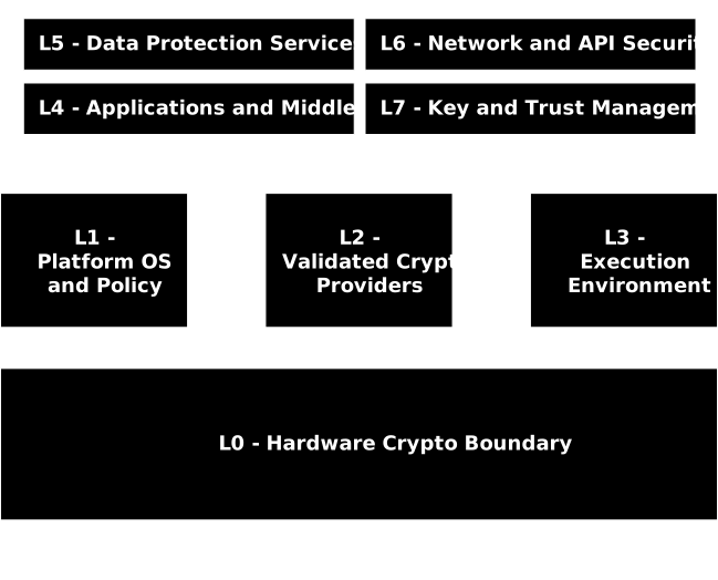
How to read the diagram
- Execution vs. policy: L4 through L6 perform cryptographic work in their domains, but they do not implement algorithms. They invoke L2 through stable APIs. L1 and L3 are not in the hot path of every operation. They set, constrain, and attest the configuration so that calls land on a validated provider in approved mode.
- Hardware delegation: When security policy or platform rules require hardware protection, L2 routes eligible operations to L0. Only public, wrapped, or handle based material leaves L0. Private key bytes do not.
- Trust and keys: L7 provides the trust and key backbone for the system. It issues and distributes anchors, certificates, and wrapping keys, and places sensitive roots in L0 where required. L2 consumes this material through approved interfaces.
- Data services: L5 centralizes encryption and integrity for data at rest by calling L2. Typical patterns include envelope encryption where L2 generates a DEK, encrypts data, and wraps the DEK under a KEK sourced from L7 and anchored in L0.
- Applications: L4 uses L2 for signing, verification, encryption, decryption, and key derivation. Verification material such as trust anchors and peer certificates is fetched from L7.
- Network and APIs: L6 terminates or originates secure channels using only approved suites. L2 supplies handshake primitives and record protection, and L7 manages credentials, stapling inputs, and resumption secrets when applicable.
Layer to Layer Dataflow Quick Map
For each caller layer, this table lists all allowed destination layers. Each layer is hyperlinked to jump to the caller's layer page which goes further in depth into each path that calls from and to the layer.
| From | To | Description of Dataflows |
|---|---|---|
| L0 | L7 | Hardware generates and protects sensitive keys, then returns handles or public material to the keystore. |
| L1 | L2, L3 | Platform pins validated crypto providers and propagates policy to runtimes. |
| L2 | L0, L7 | Provider uses hardware for key operations and returns handles or material to the keystore. |
| L3 | L2, L4, L5, L6 | Admission and runtime controls enforce provider selection and suites across app, data, and network. |
| L4 | L2, L7 | Applications consume crypto via the provider and fetch verification material from the keystore. |
| L5 | L2 | Data services centralize encryption and MAC through the provider. |
| L6 | L2 | Network layer uses approved suites and provider for TLS handshakes and channels. |
| L7 | L0, L2, L4, L5, L6 | Keystore and PKI distribute anchors and KEKs and place sensitive roots in hardware. |
Conclusion
AFIPS gives product, platform, and security teams a shared map for how approved cryptography lives in real systems. The layers clarify who owns what, where approved mode is enforced, and how evidence flows from design through operations. With this model, teams can pin validated providers, shape platform policy, and show assessors exactly how keys, ciphers, and controls are realized across the stack.
The next step is to turn the model into day-to-day work. We do that with the AFIPS Lifecycle. The lifecycle ties each layer to the activities, gates, and deliverables that move a change from intent to evidence, then back into governance. It explains when policy is written, how it is tested, what is promoted, and how runtime state is measured and attested.
The next paper in this series walks each AFIPS Lifecycle phase in detail. We will map activities to AFIPS layers, list the required controls and artifacts, and provide checklists you can reuse in federal and regulated workloads.